محفظه خلأ ( مخزن وکیوم)

محفظه خلأ (Thermal Vacuum Chamber)

محفظه خلأ محیط بسته صلبی است که توسط پمپهایی مخصوص، هرگونه گاز و هوای موجود در آن تخلیه شده تا شرایط خلأ جهت انجام آزمایشهای فیزیکی را فراهم آورد. این شرایط جهت آزمایش عملکرد تجهیزات مختلف از جمله سنجندههای فضایی کاربرد دارد.

محفظه خلأ محیط بسته صلبی است که توسط پمپ هایی مخصوص، هرگونه گاز و هوای موجود در آن تخلیه شده تا شرایط خلأ جهت انجام آزمایشهای فیزیکی را فراهم آورد. این شرایط جهت آزمایش عملکرد تجهیزات مختلف از جمله سنجنده های فضایی کاربرد دارد. نمونه های این تجهیز که از جنس آلومینیوم ساخته شده باشند، اجازه کنترل شرایط مربوط به میدانهای مغناطیسی داخل محفظه را نیز برای کاربر فراهم می آورند. در مقابل نمونه های تولید شده از جنس استیل، از تاثیر هر گونه میدان مغناطیسی در داخل محفظه جلوگیری میکنند. همچنین در کاربردهای مربوط به آزمایشگاههای سنجش از دور، امکان کنترل شرایط دمایی محفظه نیز حائز اهمیت میباشد. در قسمتهای مختلف محفظه های خلأ، معمولاً چندین مجرای ورودی و خروجی تعبیه میشود تا امکان بررسی و آزمایشهای مورد نظر بر روی تجهیز واقع شده داخل محفظه را فراهم آورد.
https://vacuumpumps.ir/
محفظه خلا جهت تست سنجنده TIRS ماهواره LandSat 8
 •
https://vacuumpumps.ir/
                       محفظه خلا تست ماهواره CHEOPS آژانس فضایی اتحادیه اروپا
 •
بطور کلی میتوان گفت که محفظه های خلأ حرارتی که در کاربردهای کالیبراسیون سنجنده های فضایی، مورد استفاده قرار می-گیرند به منظور شبیه سازی شرایط خلأ و دمای فضا، پس از پرتاب سنجنده کاربرد دارند. با قرار دادن سنجنده در این محفظه و بررسی نحوه کارکرد آن، میتوان به پیش بینی مشکلات احتمالی و نحوه پاسخدهی آن در شرایط واقعی پی برد. برخی از نمونه های این تجهیز علاوه بر شرایط خلأ و دمای شبیه سازی شده، مجهز به موتورهای دورانی جهت شبیه سازی سرعت زاویه ای وارد به سنجنده نیز میباشند. هر محفظه با بهره گیری از سیستمهای پمپاژ، سیستمهای ترموکوپل و قرائت دقیق، امکان کنترل شرایط داخلی را فراهم میآورد. همچنین جهت کنترل دمای داخل محفظه از سیستم فریز کننده Polycold  و مجموعه از گرمساز ها استفاده میشود. به همراه این تجهیز، نرم افزار جانبی و سیستم کنترل نیز ارائه میشود.
 •
 https://vacuumpumps.ir/
برخی از مدل های محفظه خلا (بدنه مرکزی)
آدرس کوتاه شده: https://isa.ir/s/mfanh0

وکیوم فرمینگ ورق ABS

وکیوم فرمینگ ورق ABS

در مرحله اول با مشخصات کامل مواد پلیمری اکریلونیتریل بوتادین استایرین یا ABS آشنا می شویم.

یکی از مهم ترین و پر مصرفترین ترپلیمرهایی که به صورت تجاری تولید میشوند ABS͵ است که در صنایع خودروسازی،الکتریکی و خانگی کاربرد فراوان دارد.

یکی از مهم ترین و پر مصرفترین ترپلیمرهایی که به صورت تجاری تولید میشوند ABS͵ است  .این ترپلیمر که از سه جزئ آکریلو نیتریل و بوتادی ان و استایرن تشکیل شده است,با تغییر در درصد هر یک از مونومر ها می توان برای  کاربری خاص اصلاح کرد.البته باید در نظر داشت در صد بیشتر به پلی استایرن اختصاص دارد. این پلیمر  را میتوان در بدنه لوازم خانگی مثل: تلفن͵ جاروبرقی͵ چایی ساز و لولزم الکتریکی و قطعات خودرو… مشاهده کرد.
مشخصات مواد پلیمری اکریلونیتریل بوتادین استایرین یا ABS (وکیوم فرمینگ ورق ABS)
نام ماده (فارسی): اکریلونیتریل بوتادین استایرین
نام ماده (انگلیسی):Acrylonitrile-butadiene-styrene
نام تجاری (فارسی): ای بی اس
نام تجاری (انگلیسی):ABS
مواد مرتبط:استایرن ، اکریلونیتریل ، پلی بوتادین
مجتمع های تولیدکننده:پتروشیمی تبریز
محل تحویل : پتروشیمی تبریز
بسته بندی : کیسه های ۲۵ کیلوگرمی سه لایه از جنس پلی اتیلن با یک لایه مشکی رنگ

نحوه تولید ABS: (وکیوم فرمینگ ورق ABS)

ABS. به وسیله روش های گوناگونی قابل تهیه است. روش اول شامل مخلوط کردن کوپلیمر مکانیکی بوتا دی ان_اکریلونیترات (BAN) با کوپلیمر استایرن_اکریلونیترات (SAN) است. گوناگونی حالت ها در مخلوط کردن SAN با پلی بوتا دی ان است. معمولا کوپلیمریزاسیون استایرن و اکریلونیترات با ترکیب با پلی بوتا دی ان به دست می آید .هر کدام از روش ها منجر به تولید پلیمری میشود که خواص بسیار برتری نسبت به پلی استایرن با مقاومت ضربه ای بالا دارد.

کاربرد ABS: (وکیوم فرمینگ ورق ABS)

در بسیاری از کاربرد هاABS به وسیله تزریق͵ قالبگیری دمشی و اکستروژن

 تولید میشود.کاربرد اصلیABS در صنایع خودرو سازی و در ساخت قطعات بدنه خودرو است.

دیگر کابرد های عمده آن شامل لوله ها و اتصالات قطعات تزریقی مانند اسباب بازی های لوگو

تلفن ها ͵بدنه لوازم خانگی و  پوشش ابزار آلات الکتریکی دستی از دیگر کاربردهای این پلاستیک است.

اسباب بازی

نکاتی در مورد بازیافت این ماده در ایران: (وکیوم فرمینگ ورق ABS)

از اصلی ترین فرآیندهای بازیافت ABS͵حرارت دهی و خرد کردن است. هنگام گرانول کردن تنظیم دما  برای جلوگیری از تخریب حرارتی و زرد شدن بسیار مهم است.

یکی از اصلی ترین مشکلاتی که در بازیافتABS رخ میدهد ͵آلودگی از جانب پلی استایرن با مقاومت ضربه ای بالا یا های ایمپکت است که تاثیرات جدی  بر روی خواص مواد بازیافتی میگذارد. در ایران این جداسازی قبل از آسیاب کردن از طریق استفاده از بنزین صورت می گیرد که اگر حل کند های ایمپکت است و اگر حل نکند ABS می باشد.اگر این مخلوط با های ایمپکت به صورت آسیابی باشد از طریق آب نمک جداسازی صورت می گیرد .در دنیا برای تفکیک با دقت بالا از روش الکتروستاتیک و کف شناوری استفاده می گردد.

لوازم خانگی

آلیاژهای ABS: (وکیوم فرمینگ ورق ABS)

تعداد زیادی از آلیاژهای متداولABS عبارتند از: آلیاژهای /PCABS با مقاومت حرارتی͵ مقاومت ضربه ای و فرآیندپذیری بهبود یافته ;آلیاژ ABS/PVC با تاخیر اندازندگی شعله و مقاومت ضربه ای بهود یافته آلیاژهای نایلون/ ABS با مقاومت شیمیایی و حرارتی بهبود یافته و آلیاژهای پلی سولفات  ABS/ با سفتی محیطی و مقاومت حرارتی و شیمیایی.

آیا این پلیمر در پتروشیمی ها ی ایران تولید می شود؟

پتروشیمی قائد بصیر و پتروشیمی تبریز از تولید کنندگان این محصول در ایران می باشند.

‌ ABS در ۵۰ گرید تولید می گردد که گریدهای معمولی ، گریدهای مقاوم در برابر حرارت ،

ضد شعله و قابل آبکاری را شامل می شود و بسیاری از این ها در پتروشیمی قائد بصیر تولید می گردد.

تولید ورق ABS و استفاده آن در بسته بندی وکیوم فرمینگ ورق ABS (وکیوم فرمینگ ورق ABS)

مواداکریلونیتریل بوتادین استایرین یا ABS که به صورت گرانول در خط تولید ورق ABS قرار می گیرد و به صورت ورق با ضخامت مشخص تولید می شود
ورق تولید شده در دستگاه وکیوم فرمینگ که می تواند دستی یا اتوماتیک باشد قرار می گیرد و با گرمای دقیق و مشخصی که به آن داده می شود و با استفاده از قالب وکیوم فرمینگ و خلاء ایجاد شده وکیوم فرمینگ ورق ABS صورت می گیرد و به دلیل سختی و محکمی در بسته بندی وکیوم فرمینگ بیشتر برای ساخت استند های رومیزی استفاده می شود.
وکیوم فرمینگ میلاد تولید کننده انواع استند های رومیزی تبلیغاتی مختلف

Dry (Oil-less) Vacuum Pumps Rotary Claw – Piston – Screw – Vane

https://asiavacuumpumps.com

Dry Claw Vacuum Pumps

Air-cooled, compact and oil free, dry claw vacuum pumps are increasingly becoming the pump of choice for medium vacuum applications. Designed for long life and ease of maintenance these pumps exhibit modern design features such as corrosion resistance and modular configuration for easy disassembly and repair.

Typically applications include CNC routing, pneumatic conveying, milking parlors ans central hospital vacuum. VFD compatible

DRY CLAW PUMPS

https://asiavacuumpumps.com

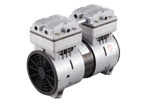
Dry Piston Vacuum Pumps

Made for laboratory or office use, these pumps are small & compact. Operating on 115v power, these pumps can operate anywhere a power outlet is available.

Applications include medical, dental, biological filtration, chip mounting/holding, air sampling, packaging and others. Flow 4.5-11.6 cfm

DRY PISTON PUMPS

https://asiavacuumpumps.com

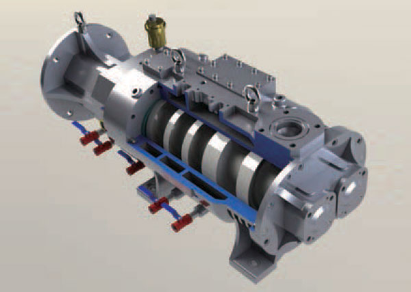
Dry Screw Vacuum Pumps

These pumps are made for process vacuum applications where heavy contaminated gas streams are present. The ability to pump heavy vapor loads and off pH gases at low pressures (<0.5mm Hg), these units are ideally suited for chemical and pharmaceutical processing, solvent reclamation, dehydration and crystallization.

Flow capacities up to 470 cfm

Innovative Vacuum and Leak Detection Solutions

Innovative Vacuum and Leak Detection Solutions

Agilent vacuum pumps, pumping systems, measurement instruments, components, and helium leak detectors allow you to create, measure, and maintain vacuum for your applications, processes, or research. Learn about Agilent’s clean, dry, quiet IDP scroll pumps, high performance, high compression TwisTorr turbo pumps, optimized, UHV/XHV ready ion pumps and controllers, and rugged, reliable helium leak detectors.

Agilent leverages its Varian Vacuum roots to fulfill your vacuum needs with product value and experienced, knowledgeable support. Agilent pumps, systems, and components enable advanced research in physics, analytical instrumentation, and nanotechnology, they are also a perfect fit for industrial processes.

Ion Pumps & Controllers

Ion Pumps and Control Units for Ultra High (UHV) and Extreme High Vacuum (XHV)

Turbo Pumps & Controllers

High Vacuum Turbo Pumps and Controllers for Optimal Vacuum Performance

Turbo Pumping Systems (TPS)

High Vacuum Turbo Pumping Systems to Optimize Vacuum in Your Laboratory or Plant

Diffusion Pumps

Oil Diffusion Vacuum Pumps for Demanding High Vacuum Applications

Dry Scroll Pumps

Clean, High Performance, Oil Free Scroll Pumps

Oil Sealed Rotary Vane Pumps

Mono and Dual Stage, Oil Sealed Rotary Vane Pumps for Broad Applications

Roots Pumps (RP) & Roots Pumping Systems (RPS)

Roots Pumps and Roots Pumping Systems to Boost Pump Down Speed

Helium Leak Detectors

Ensure Stability and Performance in Any Leak Detection Application

Vacuum Measurement

High Quality Gauges and Controllers for Accurate Vacuum Measurement

Vacuum Components

Reliable Components for your Vacuum Instruments

Vacuum & Leahttps://asiavacuumpumps.comk Detection Software

Vacuum and Leak Detection Software and App to Optimize Workflows

WHAT IS VACUUM MASS SPECTROMETRY?

WHAT IS VACUUM MASS SPECTROMETRY?

WHAT IS MASS SPECTROMETRY?

Mass spectrometry – an analytical technique that measures the mass-to-charge ratio of ions and, in forensic science, one of the best ways for toxicologists to identify and analyse substances.

In the forensic community, it’s heralded as the “gold standard” and the “near universal test” for isolating and assessing unknown agents. As a result, its widest application is in the analysis of drugs (including drug metabolites and drug paraphernalia).

THE HISTORY OF MASS SPECTROMETRY IN DRUGS AND TOXICOLOGY

Though mass spectrometers have been around for more than five decades, they remain the go-to for forensic analysis of drugs. According to the Office of Justice, drug identification remains the most frequently submitted evidence request to forensic laboratories, and mass spectrometers play a defining role in the process.

However, while mass spectrometers are widely used now, they have evolved considerably since their conception. In fact, it wasn’t until the 1950s and onwards that they really came into their own.

In the mid-1940s, mass spectrometers were far too big, expensive and difficult to operate. Some were customised to the extent operators had no idea how to use them and to make matters worse, some came with no guidance (manuals or instructions) whatsoever, making interpreting results difficult!

It wasn’t until the mid-1950s that some of these problems were resolved. In the 1950s, John H. Beynon and Fred W. McLafferty contributed to the launch of “organic mass spectrometry”, giving more guidance to users of the devices. Then in 1959 and onwards, Klaus Biemann and Carl Djerassi’s groups helped extend the capabilities of mass spectrometers, enabling them to analyse natural products and botanical extracts (including alkaloids, cannabis and cocaine).

Then, in 1968 R. J. Martin and T. G. Alexander utilised high resolution mass spectrometry (HRMS) and “cracking patterns” to help identify the hallucinogen dimethyltryptamine (DMT) in a casework sample. Analysing this problem would’ve required a major research project a few years ago – instead, it became a simple exercise problem.

By 1971, toxicologists and scientists were solving hundreds of overdose cases using gas chromatography mass spectrometry (GC-MS) and computer-assisted database searching. A group at the National Institute of Health had utilised this method – including analyses of blood serum and stomach contents – to rapidly scale the process.

A few years later (1973), a Swedish team developed a GC-MS assay for tetrahydrocannabinol in human blood that was sensitive enough to detect if someone had smoked “one half-billionth of a gram”. Mass spectrometry was evolving at an incredible rate.

Shortly after, in 1977, mass spectrometry data from the Environmental Protection Agency (EPA) was admitted as evidence in a case involving the detection of a pesticide in animal tissues. The following year a judge ruled to allow mass spectrometry test results as evidence in a capital murder case.

Fast-forward to today and mass spectrometry is widely regarded as the best available technology for the analysis of unknown agents – and dozens (between the 1940s and late 1970s) have contributed to the development of the technology – some of whom are not included in this blog.

THE HISTORY OF MASS SPECTROMETRY IN ARSON, GUNSHOT RESIDUE AND EXPLOSIVES

  • Arson

As well as drug identification, mass spectrometry is also used in cases where arson, gunshot residue and explosives are involved.

In 1959, Joseph Nicol – a firearms technician at the Chicago police crime lab – suggested that crime labs at large universities or oil companies could use the GC-MS tests for high-priority arson cases.

  • Gunshot residue (GSR) and explosives

The first tests used to determine whether or not someone had fired a gun by GSR was the “paraffin test”. This test involved pouring hot paraffin wax over a suspect’s hand and conducting a colour test on the cooled wax.

Needless to say, the test was both painful and unreliable, so alternative approaches – enter mass spectrometry – were developed, including neutron activation analysis (NAA), graphite furnace atomic absorption spectroscopy (GFA AS), GC-MS, inductively coupled plasma-MS (ICP-MS), liquid chromatography-tandem mass spectrometry (LC-MS/MS, and DESI MS/MS.

In the 1980s, GC-MS was acceptable to use in GSR cases, but the American Society for Testing and Materials (ASTM) developed a standard in 1994 that recommended scanning electron microscopy/energy dispersive x-ray spectroscopy (SEM-EDS) to determine the presence of lead, antimony and barium in the appropriate morphological particles. SEM-EDS remains the main choice for GSR.

To learn more about how vacuum technology is utilised in various fields such as medical equipment, transportation and space research, check out our guide to Vacuum Applications.

HOW MASS SPECTROMETRY IS USED FOR TRACE, FIBRES AND HAIR

The earliest applications of mass spectrometry in the analysis of trace, fibres and hair was limited in that it could only detect trace-level impurities. Due to the low concentration of inorganic elements in human hair, only the most abundant elements could be studied.

However, from the 1950s through the early 60s, spectroscopic methods like flame atomic absorption (FAA) enabled the detection of abundant metals like iron, copper and even mercury and lead in cases of poisoning.

Ion microprobe mass spectrometry (IMSS), was found to be the next reliable approach, but its application to human hair ultimately failed to meet the criteria of the time because 1) it had not acquired acceptance in the scientific community and 2) the results were not sufficiently reliable or accurate.

Next came the introduction of pyrolysis mass spectrometry (Py-MS). Pyrolysis-GC-MS (Pyr-GC-MS) was introduced to the forensic community by Saferstein et al. and Hughes et al. in their 1977 studies on man-made fibres and polymers. In fact, Pyr-GC-MS is still commonly used in today’s trace labs to study fibres and polymers – testament to its accuracy and efficacy.

THE FUTURE OF MASS SPECTROMETRY

Mass spectrometry has a rich and interesting history – particularly in the legal/forensics community where it has been able to provide some of the most reliable evidence in cases. Mass spectrometry has evolved considerably over the years and will no doubt continue to advance.

The trend today is to offer standardised procedures and solutions in instruments that deliver robust results. The operators of the mass spectrometers then do not require a scientific education but deliver data that cannot be interpreted differently in legal courses.

WHAT ARE VACUUM THIN FILMS?

WHAT ARE VACUUM THIN FILMS?

WHAT ARE THIN FILMS? 

Thin Films are layers of material on surfaces with a thickness well below a nanometer up to a micrometer. There are multiple reasons to coat a device with a thin film. These can be protective films to prevent corrosion, decorative layers on jewellery or bathroom fittings, wear protection on tools, multiple layers to improve optical properties on optics, in semiconductor or solar cell production. Many products in our daily use have coatings. Examples are smartphones and packaging foils for food; thin film technology in the automotive industry includes applications like coated reflectors in head lights and head-up displays.

Thin film coating uses several vacuum technologies like evaporation or sputtering. Both require pressures in high vacuum. Devices range from small laboratory coaters for film development to large machines for architectural glass coating.

To learn more about how vacuum technology is utilised in various fields such as medical equipment, transportation and space research, check out our guide to Vacuum Applications.

WHAT TO EXPECT FROM THE CONFERENCE

This international conference covers significant areas of vacuum technology. Topics will be

  • Applied Surface Science
  • Biointerfaces
  • Plasma Science & Technique
  • Surface Engineering
  • Surface Science
  • Thin Films
  • Vacuum Science & Technique
  • Electronic Materials and Processing
  • Nanometer Structures

شرایط نگهداری پمپ وکیوم روتاری روغنی

شرایط نگهداری پمپ وکیوم روتاری روغنی

بازرسی پمپ وکیوم پره روتاری  روغنی

۱-سطح روغن پمپ را بررسی کنید
۲-نشت روغن در کاسه نمد شافت جلو را بررسی کنید:
۳-نشت روغن بین محفظه روغن و محفظه اتصال را بررسی کنید
۴-فیلترهای روغن و اگزوز را بررسی کنید
۴-نوع روغن را مشخص کنید
۵-دمای فیلتر روغن را با دمای پوشش پمپ مقایسه کنید
۶-شرایط روغن را بررسی کنید (نمودار فقط مربوط به هیدروکربن است) وقتی روغن یک رنگ چای تیره است ، تغییر روغن لازم است (شماره ۴ – تصویر بالا را ببینید)
۷-کوپلینگ موتور را برای وجود صداهای بررسی کنید
۸-پروانه فن موتور و فن های خنک کننده را بررسی کنید
۹-فیلتر روغن را از نظر نشتی بررسی کنید
۱۰-پمپ را برای نصب سطح بررسی کنید
۱۱-فیلترهای اگزوز را بررسی کنید
۱۲-عملکرد بالست گاز / فیلتر بالاست گاز تمیز را بررسی کنید
۱۳-دام آلودگی تمیز
۱۴-عملکرد شیر برگشتی ضد مکش را بررسی کنید
۱۵-دمای پمپ را در ناحیه شیشه مشاهده کنید
۱۶-تمام واشرهای تخت را روی شاخه های تخلیه / پر کردن بصری بازرسی کنید
۱۷-شیر شناور را چک کنید (در صورت وجود)
۱۸-تسمه های محرک را از نظر سایش ، کشش بررسی کنید
۱۹-آب خنک کننده را بررسی کنید (در صورت وجود)
۲۰-مبدل حرارتی / پمپ را از نظر نشت آب بررسی کنید (در صورت وجود)
۲۱-خواندن دما را در شیر حرارتی بررسی کنید
۲۲-تمیز کردن رادیاتور / جریان هوا را بررسی کنید
۲۳-تمیزکاری محلی که پمپ در آن استفاده می شود را بصری بررسی و ثبت کنید
برای کسب راهنمایی بیشتر در مورد کار با پمپ های چرخشی

۰۲۱-۶۶۷۹۱۷۷۵

۰۲۱-۶۶۷۹۱۷۷۶

چگونگی تکامل علم وکیوم(خلا)

چگونگی تکامل علم وکیوم(خلا)

تکامل علم خلاuum که از قرن هفدهم آغاز شد ، بسیاری از دستاوردهای علمی دیگر را منعکس کرده است ، از جمله توسعه قوانین گاز و کشف الکترون. با این وجود ، دنیای وکیوم هنوز هم مهندسان و دانشمندان را هیجان زده و جلب می کند. در واقع ، تحولات اساسی همچنان مرزهای این موضوع جذاب را تحت فشار قرار می دهند.

فیزیک خلاuum – اصطلاحات اساسی
واحدهای فشار

واحد فشار خلاuum چیست؟

در زیر یک نمای کلی از واحدهای اصلی فشار و تبدیل واحدهای فشار آورده شده است:
واحدهای فشار و تبدیل ها


محدوده های خلاAC

در علوم خلاuum تقسیم دامنه فشار به پنج رژیم فردی معمول است:

خلا R خشن (یا کم) (R): جوی تا ۱ mbar

خلا متوسط ​​(یا خوب) (MV): 1 تا ۱۰–۳ mbar

خلا High زیاد (HV): 10–۳ تا ۱۰–۷ mbar

خلاuum فوق العاده زیاد (UHV): 10–۷ تا ۱۰–۱۲ mbar

خلا High شدید (XHV): بیش از ۱۰-۱۲ mbar.

این تقسیم بندی ها تا حدودی خودسرانه است ، و رشته های مختلف مهندسی از تعاریف خاص خود استفاده می کنند ، یعنی شیمی دانان اغلب از طیف مورد علاقه خود (۱۰۰ تا ۱ mbar) به عنوان “خلا inter میانی” یاد می کنند ، در حالی که برخی از مهندسان ممکن است خلا را “کم فشار “یا” فشار منفی “.


انواع جریان
فناوری خلاuum معمولاً با سه نوع جریان همراه است: جریان ویسکوز یا پیوسته. جریان مولکولی و یک محدوده انتقالی بین این دو معروف به جریان Knudsen.

جریان ویسکوز (یا پیوسته) در محدوده خلا rough خشن یافت می شود و با تعامل نزدیک مولکول ها تعیین می شود. سه زیرشاخه جریان چسبناک وجود دارد: “جریان آشفته” (اگر حرکت گرداب در روند جریان ظاهر شود) ؛ “جریان پوزویل” که در آن لایه ها روی یکدیگر می کشند (که این اغلب در خلا ها وجود دارد). و “جریان خفه” که هنگام تخلیه مخازن خلاuum یا در صورت نشت وجود دارد.

وقتی مولکولها بتوانند آزادانه حرکت کنند ، بدون هیچ گونه تداخل متقابل ، جریان مولکولی در خلاuum زیاد و فوق العاده زیاد (UHV) غالب است. جریان مولکولی در جایی وجود دارد که میانگین مسیر آزاد یک مولکول ƛ تعریف شده به عنوان میانگین مسافت طی شده توسط مولکول ها بین برخوردها) بسیار بزرگتر از قطر لوله است.

جریان نودسن محدوده انتقالی بین جریان چسبناک و مولکولی است. این در محدوده خلا متوسط ​​است که در آن طول مسیر آزاد یک مولکول مشابه قطر لوله است.

نمودار جریان در خلا

در جریان چسبناک ، حرکت ترجیحی مولکول های گاز یکسان با جهت ماکروسکوپی جریان گاز خواهد بود ، زیرا ذرات به طور فشرده بسته بندی شده اند و بسیار بیشتر از دیواره های مرزی با یکدیگر برخورد می کنند. با این حال ، در جریان مولکولی ، ذراتی که با دیواره ها برخورد می کنند غالب هستند.

در خلاuهای خشن ، برخورد ذرات گاز غالباً اتفاق می افتد ، در حالی که در خلا vacهای زیاد و بسیار زیاد ، برخورد ذرات گاز با دیواره های ظرف غالب است.


رفتار
تمام اتصالات بین مصرف سیستم پمپ و محفظه منجر به کاهش سرعت پمپاژ می شود. جریان pV از طریق هر عنصر لوله کشی مورد نظر ، مانند لوله یا شیلنگ ، دریچه ها ، نازل ها ، دهانه های دیواره بین دو رگ و غیره ، با

جریان سرعت پمپاژ از طریق معادله

در اینجا Δp = (p1 – p2) دیفرانسیل فشار بین انتهای ورودی و خروجی عنصر لوله کشی است. ضریب تناسب C به عنوان مقدار رسانایی یا به سادگی “رسانایی” تعیین می شود. در محدوده جریان مولکولی ، C یک ثابت است که مستقل از فشار است. در محدوده جریان انتقالی و چسبناک ، برعکس ، به فشار بستگی دارد. در نتیجه ، محاسبه C برای عناصر لوله کشی باید به طور جداگانه برای محدوده فشار فردی انجام شود.

از معادله فوق اغلب به عنوان “قانون اهم برای فناوری خلا” یاد می شود که در آن qpV با جریان ، Δp ولتاژ و C با مقدار هدایت الکتریکی مطابقت دارد. مشابه قانون اهم در علم الکتریسیته ، مقاومت در برابر جریان

به عنوان مقدار متقابل ارزش هدایت معرفی شده است:

عکس – ۷

بنابراین می توان معادله را به صورت زیر نوشت:

جریان سرعت پمپاژ از طریق معادله

اگر اجزا به طور موازی به هم متصل شوند ، موارد زیر اعمال می شود:

عکس – ۹

برای اجزای متصل به صورت سری موارد زیر اعمال می شود:

عکس – ۱۰


محدوده های فشار استفاده شده در فن آوری خلاAC و مشخصات آنها
دامنه های فشار مورد استفاده در فناوری خلا و خصوصیات آنها


برای اطلاعات بیشتر در مورد ویژگی های مختلف ، روی لینک زیر کلیک کنید تا کتاب الکترونیکی ما را بارگیری کنید:

کتاب اصول تولید خلا generation
تولید خلاuum
پارامترهای پمپ
سرعت پمپاژ
معادله سرعت پمپاژ (جریان میزان ولتاژ) در سیستم خلاuum

سرعت جریان حجم (qV) یا سرعت پمپاژ (S) سرعت جریان حجمی حجم (خالص) یا حجم گاز تخلیه شده در واحد زمان (m3 / s ، l / s ، cfm ، m3 / h…) است. این در ورودی پمپ اندازه گیری می شود و به گونه های گاز ، بخار و غیره بستگی دارد.


توان پمپ
ظرفیت پمپاژ (توان خروجی) برای پمپ برابر است با جریان جرم از طریق پورت ورودی پمپ:

How do you define a vacuum system?

How do you define a vacuum system?

In basic terms the pressure of a gas is provided by the physical presence (and the movement) of molecules. By reducing the number of molecules and/or their natural tendency to move, the pressure of a gas is reduced. For this explanation, any pressure that is less than normal atmospheric pressure is indicative of a vacuum.

In the world of vacuums, there are significant differences between those at the lower end of the spectrum and those that occupy the higher (i.e. high vacuum) levels. In terms of definitions: vacuums that range between atmospheric pressure and 1 mbar are known as “rough” vacuums, whilst pressures from 1 to 10-3 mbar are known as medium vacuums. Thereafter, the vacuum definitions progress from high to ultra-high vacuums (UHVs) through to extremely high vacuums (XHVs) and range from 10-3 to 10-12 mbar.

How to choose the right vacuum pump for your application

Choosing the right vacuum pump is not an easy undertaking. However, before embarking upon the vacuum simulation process, there is a fundamental truth which needs to be accepted: no single pump will match all your requirements or expectations. Nevertheless, the process (should) start with a clear view of the vacuum range you are trying to obtain, as well as the use to which the vacuum will be put (which in itself will provide an indication of the capacities required). From this basic bedrock of requirements stretches out a further series of “stepping stones” (some significant, others less so) including noise and vibration considerations, ease of maintenance, up-front and on-going costs, the size (i.e. footprint) of the pump itself, its resistance to shock, tolerance to particle intrusion and whether oil contamination would be an issue. By scrutinising this menu of requirements and restrictions, the vacuum engineer ought to be able to hone-in onto the most suitable vacuum pump for the task in hand.

There are a large number of vacuum pumps which cater for the lower (i.e. rough and medium) vacuum range, including the diaphragm pump at one end of the spectrum through to the screw, rotary and roots pumps at the medium vacuum end.

The types of pumps employed for rough and medium vacuums (when compared to high through to XHV pumps) are fairly simple in terms of the vacuum system operation. However, that is not to underestimate the precise engineering required (or indeed the science) behind their workings. Furthermore, it should not be forgotten that many of these pumps are employed as fore (or backing) pumps, which are employed to “charge” higher level vacuum pumps. Without the benefit of such fore-pumps, these higher vacuum units would at best – operate sluggishly and slowly, and at worst – not at all.

Diaphragm pumps, which operate from 103 to 1 mbar, employ a rod which oscillates backwards and forwards compressing the gas contained within a flexible pipe/chamber. This oscillation activates (alternatively) either an inlet or an exit valve.

Diaphragm pump


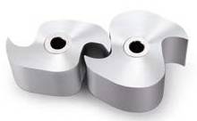
Roots pumps employ two counter-rotating, interconnecting units rotating within a chamber. Gas enters through the intake flange and is “pinched” between the two rapidly rotating units and the chamber wall, and is then expelled through the exhaust port.


Roots booster pump


Scroll pumps use two inter-wound Archimedean spiral-shaped scrolls (one fixed, whilst the other orbits eccentrically) to pump or compress liquids/gases. Scroll pumps are used where clean, dry vacuum pumping is required.


Scroll pump cross section


Rotary vane pumps work in the following manner: an offset rotor (fitted with vanes that slide in and out of their housing) rotates within a chamber. The vanes, which seal against the inside of the circular chamber, “trap” in a quantity of gas which enters through an inlet port. As the rotor rotates, the volume contained between the vanes and the inside surface of the chamber decreases, so the pressure of the “captured” gas likewise decreases, until it exits through the outlet port.


Rotary van pump


Screw pumps employ two screw rotors which are engineered to rotate “in on each other”, thereby trapping the gas in the void between the “screws” of their rotors. As they rotate, the void between the screws decreases which not only compresses the gas, but also forces it towards the exit portal.


Multistage roots pump


High & Extremely-High Vacuum Pumps

The high-vacuum, UHV and XHV range of pumps are by-and-large dominated by four completely different genres: the turbomolecular pump, the ion getter pump, the cryo pump and the diffusion pump.

Turbomolecular pumps use a very fast spinning rotor not dissimilar to a multi-bladed turbine. The high-speed impact of blades directly onto gas molecules “directs” these molecules towards the “exit” part of the chamber.


turbomolecular pump


Ion getter pumps are effectively repeat units of penning cells sustaining a plasma discharge. Once initiated the discharge. A high potential accelerates the electron toward an anode, but a high magnetic field causes a spiral motion. A dense electron cloud becomes trapped in the anode cylinder. Many ionizing collisions occur with gas molecules. The positive ions are attracted toward the cathode where they can become embedded and causes a sputtering of titanium from the cathode. This active layer pumps molecules by gettering.


IZ_GAMMA_3 cropped-1


Cryo pumps either condense or absorb gases within a three-stage, but two-part vacuum chamber; there are no moving parts. The vacuum is acquired using low-temperatures, provided by a dual-stage cold head. The two functions (condensation and adsorption) operate in parallel.

Diffusion pumps use a directed high speed vapour jet to direct gas molecules in the pump throat down into the bottom of the pump and out to the exhaust. They were named because the design was based on the fact that gas cannot diffuse against the vapor jet, but will be carried with it to the exhaust.

diffusion pumps

Interested in learning more about the different vacuum pumping technologies? Then why not download our eBook:


Vacuum System Simulation & Design

Choosing the right vacuum pump, may seem like a daunting (long-winded and costly) exercise–which is where engineering simulation comes in. By putting values to each uncertainty and sign-posting every decision node, simulation has taken much of the wasteful cost and iterative guesswork out of what has traditionally been the tortuous process of vacuum pump and vacuum simulation.

Engineering simulation (or modelling) is a well-established practice and methodology whereby a substitute for physical experimentation is created, allowing mathematical values to be calculated and then employed to describe how a system and/or a process may (or may not) perform.

This table-top, computer assisted exercise is conducted before any components are purchased, and before the system/process path and sequence have been confirmed. In its simplest terms, simulation/modelling can identify problems and anomalies in the design stage, thus eliminating the orthodox but out-dated and wasteful “design-build-test-redesign” cycle.

The technical characteristics of the various components of a system (that may be employed) are put together into a “trial” system, and a simulated performance is then computer-run to ascertain a number of parameters, including whether: the components are compatible; the system produces the required outcome; the entity operates safely; the results are reliable/repeatable; and if component substitution could produce better results. Furthermore, simulation can highlight any weaknesses (either in components or configurations), as well as providing an indication of any process/system.


The Challenges & Implications of Vacuum Simulation and Operation

The major advantage of engineering simulation is that all this (pre-work) can be carried out without having to go to the expense of actually purchasing expensive components (which may prove to be unsuitable or redundant) or, indeed, having to engineer/assemble the system at this embryonic stage.

It must be appreciated that vacuum simulation is not without its drawbacks.

Vacuum simulation calculations assume that the system is in a steady state. However, whilst such steady state simulation is fast, stable and accurate for simple system models, it fails to account for the misconception that throughput is in fact not constant throughout the system. In simple cases this disparity creates an acceptably small error, but in more complex systems, the error can be significant. Additionally, such “steady state models” are not suitable for systems with dynamic pumps, or for primary pumps/secondary booster combinations, which slow down at high-inlet pressures.

Furthermore, it must be appreciated that, as with many procedures, there is never a true substitute for “the real thing”. Whilst simulation will – at the very least- “shave off” some of the imperfections of a system or poor/incompatible item choices, there is really no cast iron guarantee that additional refinements or re-engineering of components and processes will not further perfect the final system.

Need help with your vacuum simulation project? Get in touch with our experts today for a free no-obligation consultation:


Vacuum Simulation Tools

There are a number of specialist simulation software tools available to the vacuum fraternity.

PumpCalc is a simulation package for “simple systems” (i.e. those that consist of a chamber, a foreline and a pump set), with the “pressure” time from pump output to the chamber being small enough so that speed and conductance are approximately constant. Whilst PumpCalc is best suited for simple systems, it can still be used on more complex systems, if symmetry can be used to simplify the entirety.

TransCalc is a network-based computational simulation software package for the design of vacuum systems. TransCalc is based upon duct-flow prediction techniques which provide a solution across all pressure ranges (including turbulent, compressable and transitional flow). Compared to steady-state models, TransCalc uses fewer primary assumptions about the system, calculates pipe flows based on whole-system throughput and, furthermore, modifies pressures by conserving throughput over a short time interval.

Pascal is a smart simulation tool enables the engineering of a flow-optimisation pump system using empirical data gained from existing pumps, which is coupled with data from the components required to complete the vacuum system, and then through simulation allows the study of three-dimensional molecular flow through the whole unit. Then, by using existing CAD data the simulation software can calculate the characteristics of the entire vacuum system, allowing flow engineering to be optimised.

Pascal simulation software

MolFlow is a Monte-Carlo simulator package developed at CERN, which provides insight into the behaviour of vacuum systems. MolFlow can show the distribution of the number of gas bounces, the flight distance and the flight time of test particles.

VacSim is a PC-based software simulation package which uses the hermetic capture of a vacuum system and is able to predict/calculate how the system pressure varies with time, throughput volumes, pump speed and oil back-streaming. VacSim is able to produce pump-down curves, show the impact of bakeout regimes, illustrate the impact of (construction) material and demonstrate what difference a pump change will make.

VacSim is perhaps not as sophisticated as some vacuum simulation packages but makes up for this by its inherent simplicity and its ease-of-use.

COMSOL can trace its development from 1986 at the Royal Institute of Technology in Stockholm, Sweden. It is used for vacuum system simulation including those used in semi-conductor processing, particle acceleration and mass spectrometers. Small channel applications (such as shale gas exploration and gas flow in nano-porous materials) can also be simulated.

ANSYS is a stress analysis CAD-type finite element (FE) analysis software package that provides a multi-coloured graphic image that can assist in the balancing of rotors, seismic simulation, model analysis, non-linear stress (i.e. creep and/or fatigue modelling), all of which are important in ensuring product reliability and safety. In addition to traditional stress analysis, ANSYS also has a thermal capability that provides a visual model of thermal distortion in pump components, evaluates cooling (thus highlighting cool spots which can lead to condensation), and enables multi-physics modelling (by coupling stress and magnetic analysis).