WHAT IS VACUUM MASS SPECTROMETRY?
WHAT IS MASS SPECTROMETRY?
Mass spectrometry – an analytical technique that measures the mass-to-charge ratio of ions and, in forensic science, one of the best ways for toxicologists to identify and analyse substances.
In the forensic community, it’s heralded as the “gold standard” and the “near universal test” for isolating and assessing unknown agents. As a result, its widest application is in the analysis of drugs (including drug metabolites and drug paraphernalia).
THE HISTORY OF MASS SPECTROMETRY IN DRUGS AND TOXICOLOGY
Though mass spectrometers have been around for more than five decades, they remain the go-to for forensic analysis of drugs. According to the Office of Justice, drug identification remains the most frequently submitted evidence request to forensic laboratories, and mass spectrometers play a defining role in the process.
However, while mass spectrometers are widely used now, they have evolved considerably since their conception. In fact, it wasn’t until the 1950s and onwards that they really came into their own.
In the mid-1940s, mass spectrometers were far too big, expensive and difficult to operate. Some were customised to the extent operators had no idea how to use them and to make matters worse, some came with no guidance (manuals or instructions) whatsoever, making interpreting results difficult!
It wasn’t until the mid-1950s that some of these problems were resolved. In the 1950s, John H. Beynon and Fred W. McLafferty contributed to the launch of “organic mass spectrometry”, giving more guidance to users of the devices. Then in 1959 and onwards, Klaus Biemann and Carl Djerassi’s groups helped extend the capabilities of mass spectrometers, enabling them to analyse natural products and botanical extracts (including alkaloids, cannabis and cocaine).
Then, in 1968 R. J. Martin and T. G. Alexander utilised high resolution mass spectrometry (HRMS) and “cracking patterns” to help identify the hallucinogen dimethyltryptamine (DMT) in a casework sample. Analysing this problem would’ve required a major research project a few years ago – instead, it became a simple exercise problem.
By 1971, toxicologists and scientists were solving hundreds of overdose cases using gas chromatography mass spectrometry (GC-MS) and computer-assisted database searching. A group at the National Institute of Health had utilised this method – including analyses of blood serum and stomach contents – to rapidly scale the process.
A few years later (1973), a Swedish team developed a GC-MS assay for tetrahydrocannabinol in human blood that was sensitive enough to detect if someone had smoked “one half-billionth of a gram”. Mass spectrometry was evolving at an incredible rate.
Shortly after, in 1977, mass spectrometry data from the Environmental Protection Agency (EPA) was admitted as evidence in a case involving the detection of a pesticide in animal tissues. The following year a judge ruled to allow mass spectrometry test results as evidence in a capital murder case.
Fast-forward to today and mass spectrometry is widely regarded as the best available technology for the analysis of unknown agents – and dozens (between the 1940s and late 1970s) have contributed to the development of the technology – some of whom are not included in this blog.
THE HISTORY OF MASS SPECTROMETRY IN ARSON, GUNSHOT RESIDUE AND EXPLOSIVES
As well as drug identification, mass spectrometry is also used in cases where arson, gunshot residue and explosives are involved.
In 1959, Joseph Nicol – a firearms technician at the Chicago police crime lab – suggested that crime labs at large universities or oil companies could use the GC-MS tests for high-priority arson cases.
- Gunshot residue (GSR) and explosives
The first tests used to determine whether or not someone had fired a gun by GSR was the “paraffin test”. This test involved pouring hot paraffin wax over a suspect’s hand and conducting a colour test on the cooled wax.
Needless to say, the test was both painful and unreliable, so alternative approaches – enter mass spectrometry – were developed, including neutron activation analysis (NAA), graphite furnace atomic absorption spectroscopy (GFA AS), GC-MS, inductively coupled plasma-MS (ICP-MS), liquid chromatography-tandem mass spectrometry (LC-MS/MS, and DESI MS/MS.
In the 1980s, GC-MS was acceptable to use in GSR cases, but the American Society for Testing and Materials (ASTM) developed a standard in 1994 that recommended scanning electron microscopy/energy dispersive x-ray spectroscopy (SEM-EDS) to determine the presence of lead, antimony and barium in the appropriate morphological particles. SEM-EDS remains the main choice for GSR.
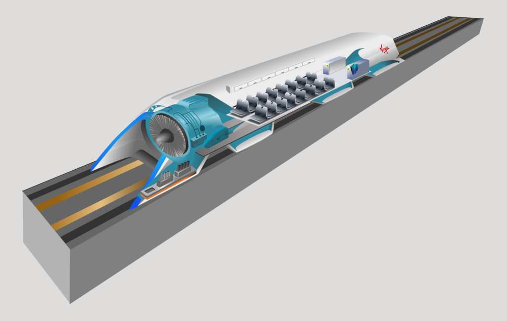
To learn more about how vacuum technology is utilised in various fields such as medical equipment, transportation and space research, check out our guide to Vacuum Applications.
HOW MASS SPECTROMETRY IS USED FOR TRACE, FIBRES AND HAIR
The earliest applications of mass spectrometry in the analysis of trace, fibres and hair was limited in that it could only detect trace-level impurities. Due to the low concentration of inorganic elements in human hair, only the most abundant elements could be studied.
However, from the 1950s through the early 60s, spectroscopic methods like flame atomic absorption (FAA) enabled the detection of abundant metals like iron, copper and even mercury and lead in cases of poisoning.
Ion microprobe mass spectrometry (IMSS), was found to be the next reliable approach, but its application to human hair ultimately failed to meet the criteria of the time because 1) it had not acquired acceptance in the scientific community and 2) the results were not sufficiently reliable or accurate.
Next came the introduction of pyrolysis mass spectrometry (Py-MS). Pyrolysis-GC-MS (Pyr-GC-MS) was introduced to the forensic community by Saferstein et al. and Hughes et al. in their 1977 studies on man-made fibres and polymers. In fact, Pyr-GC-MS is still commonly used in today’s trace labs to study fibres and polymers – testament to its accuracy and efficacy.
THE FUTURE OF MASS SPECTROMETRY
Mass spectrometry has a rich and interesting history – particularly in the legal/forensics community where it has been able to provide some of the most reliable evidence in cases. Mass spectrometry has evolved considerably over the years and will no doubt continue to advance.
The trend today is to offer standardised procedures and solutions in instruments that deliver robust results. The operators of the mass spectrometers then do not require a scientific education but deliver data that cannot be interpreted differently in legal courses.


.jpg?width=499&name=ECODRY_Rotor_Screws%20(1).jpg)